A Tesla coil is an electrical resonant transformer circuit designed by inventor Nikola Tesla in 1891.[1][2] It is used to produce high-voltage, low-current, high frequency alternating-current electricity.[3][4][5][6][7][8][9] Tesla experimented with a number of different configurations consisting of two, or sometimes three, coupled resonant electric circuits.

Tesla used these circuits to conduct innovative experiments in electrical lighting, phosphorescence, X-ray generation, high frequency alternating current phenomena, electrotherapy, and the transmission of electrical energy without wires. Tesla coil circuits were used commercially in sparkgap radio transmitters for wireless telegraphy until the 1920s,[1][10][11][12][13][14] and in medical equipment such as electrotherapy and violet ray devices. Today, their main usage is for entertainment and educational displays, although small coils are still used as leak detectors for high vacuum systems.[9][15][16]
Operation
Types
History
Electrical oscillation and resonant air-core transformer circuits had been explored before Tesla.[47][46] Resonant circuits using Leyden jars were invented beginning in 1826 by Felix Savary, Joseph Henry, William Thomson, and Oliver Lodge.[48] and Henry Rowland built a resonant transformer in 1889.[41] Elihu Thomson invented the Tesla coil circuit independently at the same time Tesla did.[49][50][51][40] Tesla patented his Tesla coil circuit April 25, 1891.[52][2] and first publicly demonstrated it May 20, 1891 in his lecture "Experiments with Alternate Currents of Very High Frequency and Their Application to Methods of Artificial Illumination" before the American Institute of Electrical Engineers at Columbia College, New York.[53][54][44] Although Tesla patented many similar circuits during this period, this was the first that contained all the elements of the Tesla coil: high voltage primary transformer, capacitor, spark gap, and air core "oscillation transformer".
Modern-day Tesla coils

Modern high-voltage enthusiasts usually build Tesla coils similar to some of Tesla's "later" 2-coil air-core designs. These typically consist of a primary tank circuit, a series LC (inductance-capacitance) circuit composed of a high-voltage capacitor, spark gap and primary coil, and the secondary LC circuit, a series-resonant circuit consisting of the secondary coil plus a terminal capacitance or "top load". In Tesla's more advanced (magnifier) design, a third coil is added. The secondary LC circuit is composed of a tightly coupled air-core transformer secondary coil driving the bottom of a separate third coil helical resonator. Modern 2-coil systems use a single secondary coil. The top of the secondary is then connected to a topload terminal, which forms one 'plate' of a capacitor, the other 'plate' being the earth (or "ground"). The primary LC circuit is tuned so that it resonates at the same frequency as the secondary LC circuit. The primary and secondary coils are magnetically coupled, creating a dual-tuned resonant air-core transformer. Earlier oil-insulated Tesla coils needed large and long insulators at their high-voltage terminals to prevent discharge in air. Later Tesla coils spread their electric fields over larger distances to prevent high electrical stresses in the first place, thereby allowing operation in free air. Most modern Tesla coils also use toroid-shaped output terminals. These are often fabricated from spun metal or flexible aluminum ducting. The toroidal shape helps to control the high electrical field near the top of the secondary by directing sparks outward and away from the primary and secondary windings.
A more complex version of a Tesla coil, termed a "magnifier" by Tesla, uses a more tightly coupled air-core resonance "driver" transformer (or "master oscillator") and a smaller, remotely located output coil (called the "extra coil" or simply the resonator) that has a large number of turns on a relatively small coil form. The bottom of the driver's secondary winding is connected to ground. The opposite end is connected to the bottom of the extra coil through an insulated conductor that is sometimes called the transmission line. Since the transmission line operates at relatively high RF voltages, it is typically made of 1" diameter metal tubing to reduce corona losses. Since the third coil is located some distance away from the driver, it is not magnetically coupled to it. RF energy is instead directly coupled from the output of the driver into the bottom of the third coil, causing it to "ring up" to very high voltages. The combination of the two-coil driver and third coil resonator adds another degree of freedom to the system, making tuning considerably more complex than that of a 2-coil system. The transient response for multiple resonance networks (of which the Tesla magnifier is a sub-set) has only recently been solved.[55] It is now known that a variety of useful tuning "modes" are available, and in most operating modes the extra coil will ring at a different frequency than the master oscillator.[56]
Primary switching
 Play media
Modern transistor or vacuum tube Tesla coils do not use a primary spark gap. Instead, the transistor(s) or vacuum tube(s) provide the switching or amplifying function necessary to generate RF power for the primary circuit. Solid-state Tesla coils use the lowest primary operating voltage, typically between 155 and 800 volts, and drive the primary winding using either a single, half-bridge, or full-bridge arrangement of bipolar transistors, MOSFETs or IGBTs to switch the primary current. Vacuum tube coils typically operate with plate voltages between 1500 and 6000 volts, while most spark gap coils operate with primary voltages of 6,000 to 25,000 volts. The primary winding of a traditional transistor Tesla coil is wound around only the bottom portion of the secondary coil. This configuration illustrates operation of the secondary as a pumped resonator. The primary 'induces' alternating voltage into the bottom-most portion of the secondary, providing regular 'pushes' (similar to providing properly timed pushes to a playground swing). Additional energy is transferred from the primary to the secondary inductance and top-load capacitance during each "push", and secondary output voltage builds (called 'ring-up'). An electronic feedback circuit is usually used to adaptively synchronize the primary oscillator to the growing resonance in the secondary, and this is the only tuning consideration beyond the initial choice of a reasonable top-load.
In a dual resonant solid-state Tesla coil (DRSSTC), the electronic switching of the solid-state Tesla coil is combined with the resonant primary circuit of a spark-gap Tesla coil. The resonant primary circuit is formed by connecting a capacitor in series with the primary winding of the coil, so that the combination forms a series tank circuit with a resonant frequency near that of the secondary circuit. Because of the additional resonant circuit, one manual and one adaptive tuning adjustment are necessary. Also, an interrupter is usually used to reduce the duty cycle of the switching bridge, to improve peak power capabilities; similarly, IGBTs are more popular in this application than bipolar transistors or MOSFETs, due to their superior power handling characteristics. A current-limiting circuit is usually used to limit maximum primary tank current (which must be switched by the IGBT's) to a safe level. Performance of a DRSSTC can be comparable to a medium-power spark-gap Tesla coil, and efficiency (as measured by spark length versus input power) can be significantly greater than a spark-gap Tesla coil operating at the same input power.
Practical aspects of design
High voltage production


A large Tesla coil of more modern design often operates at very high peak power levels, up to many megawatts (millions of watts, equivalent to hundreds of thousands of horsepower). It is therefore adjusted and operated carefully, not only for efficiency and economy, but also for safety. If, due to improper tuning, the maximum voltage point occurs below the terminal, along the secondary coil, a discharge (spark) may break out and damage or destroy the coil wire, supports, or nearby objects.
Tesla experimented with these, and many other, circuit configurations (see right). The Tesla coil primary winding, spark gap and tank capacitor are connected in series. In each circuit, the AC supply transformer charges the tank capacitor until its voltage is sufficient to break down the spark gap. The gap suddenly fires, allowing the charged tank capacitor to discharge into the primary winding. Once the gap fires, the electrical behavior of either circuit is identical. Experiments have shown that neither circuit offers any marked performance advantage over the other.
However, in the typical circuit, the spark gap's short circuiting action prevents high-frequency oscillations from 'backing up' into the supply transformer. In the alternate circuit, high amplitude high frequency oscillations that appear across the capacitor also are applied to the supply transformer's winding. This can induce corona discharges between turns that weaken and eventually destroy the transformer's insulation. Experienced Tesla coil builders almost exclusively use the top circuit, often augmenting it with low pass filters (resistor and capacitor (RC) networks) between the supply transformer and spark gap to help protect the supply transformer. This is especially important when using transformers with fragile high-voltage windings, such as neon sign transformers (NSTs). Regardless of which configuration is used, the HV transformer must be of a type that self-limits its secondary current by means of internal leakage inductance. A normal (low leakage inductance) high-voltage transformer must use an external limiter (sometimes called a ballast) to limit current. NSTs are designed to have high leakage inductance to limit their short circuit current to a safe level.
Tuning
The primary coil's resonant frequency is tuned to that of the secondary, by using low-power oscillations, then increasing the power (and retuning if necessary) until the system operates properly at maximum power. While tuning, a small projection (called a "breakout bump") is often added to the top terminal in order to stimulate corona and spark discharges (sometimes called streamers) into the surrounding air. Tuning can then be adjusted so as to achieve the longest streamers at a given power level, corresponding to a frequency match between the primary and secondary coil. Capacitive "loading" by the streamers tends to lower the resonant frequency of a Tesla coil operating under full power. A toroidal topload is often preferred to other shapes, such as a sphere. A toroid with a major diameter that is much larger than the secondary diameter provides improved shaping of the electrical field at the topload. This provides better protection of the secondary winding (from damaging streamer strikes) than a sphere of similar diameter. And, a toroid permits fairly independent control of topload capacitance versus spark breakout voltage. A toroid's capacitance is mainly a function of its major diameter, while the spark breakout voltage is mainly a function of its minor diameter. A grid dip oscillator (GDO) is sometimes used to help facilitate initial tuning and aid in design. The resonant frequency of the secondary can be difficult to determine except by using a GDO or other experimental method, whereas the physical properties of the primary more closely represent lumped approximations of RF tank design. In this schema the secondary is built somewhat arbitrarily in imitation of other successful designs, or entirely so with supplies on hand, its resonant frequency is measured and the primary designed to suit.
Air discharges

In coils that produce air discharges, such as those built for entertainment, electrical energy from the secondary and toroid is transferred to the surrounding air as electrical charge, heat, light, and sound. The process is similar to charging or discharging a capacitor, except that a Tesla coil uses AC instead of DC. The current that arises from shifting charges within a capacitor is called a displacement current. Tesla coil discharges are formed as a result of displacement currents as pulses of electrical charge are rapidly transferred between the high-voltage toroid and nearby regions within the air (called space charge regions). Although the space charge regions around the toroid are invisible, they play a profound role in the appearance and location of Tesla coil discharges.
When the spark gap fires, the charged capacitor discharges into the primary winding, causing the primary circuit to oscillate. The oscillating primary current creates an oscillating magnetic field that couples to the secondary winding, transferring energy into the secondary side of the transformer and causing it to oscillate with the toroid capacitance to ground. Energy transfer occurs over a number of cycles, until most of the energy that was originally in the primary side is transferred to the secondary side. The greater the magnetic coupling between windings, the shorter the time required to complete the energy transfer. As energy builds within the oscillating secondary circuit, the amplitude of the toroid's RF voltage rapidly increases, and the air surrounding the toroid begins to undergo dielectric breakdown, forming a corona discharge.
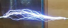
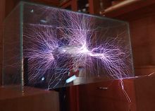
As the secondary coil's energy (and output voltage) continue to increase, larger pulses of displacement current further ionize and heat the air at the point of initial breakdown. This forms a very electrically conductive "root" of hotter plasma, called a leader, that projects outward from the toroid. The plasma within the leader is considerably hotter than a corona discharge, and is considerably more conductive. In fact, its properties are similar to an electric arc. The leader tapers and branches into thousands of thinner, cooler, hair-like discharges (called streamers). The streamers look like a bluish 'haze' at the ends of the more luminous leaders. The streamers transfer charge between the leaders and toroid to nearby space charge regions. The displacement currents from countless streamers all feed into the leader, helping to keep it hot and electrically conductive.
The primary break rate of sparking Tesla coils is slow compared to the resonant frequency of the resonator-topload assembly. When the switch closes, energy is transferred from the primary LC circuit to the resonator where the voltage rings up over a short period of time up culminating in the electrical discharge. In a spark gap Tesla coil, the primary-to-secondary energy transfer process happens repetitively at typical pulsing rates of 50–500 times per second, depending on the frequency of the input line voltage. At these rates, previously-formed leader channels do not get a chance to fully cool down between pulses. So, on successive pulses, newer discharges can build upon the hot pathways left by their predecessors. This causes incremental growth of the leader from one pulse to the next, lengthening the entire discharge on each successive pulse. Repetitive pulsing causes the discharges to grow until the average energy available from the Tesla coil during each pulse balances the average energy being lost in the discharges (mostly as heat). At this point, dynamic equilibrium is reached, and the discharges have reached their maximum length for the Tesla coil's output power level. The unique combination of a rising high-voltage radio frequency envelope and repetitive pulsing seem to be ideally suited to creating long, branching discharges that are considerably longer than would be otherwise expected by output voltage considerations alone. High-voltage, low-energy discharges create filamentary multibranched discharges which are purplish-blue in colour. High-voltage, high-energy discharges create thicker discharges with fewer branches, are pale and luminous, almost white, and are much longer than low-energy discharges, because of increased ionisation. A strong smell of ozone and nitrogen oxides will occur in the area. The important factors for maximum discharge length appear to be voltage, energy, and still air of low to moderate humidity. There are comparatively few scientific studies about the initiation and growth of pulsed lower-frequency RF discharges, so some aspects of Tesla coil air discharges are not as well understood when compared to DC, power-frequency AC, HV impulse, and lightning discharges.
Applications
Today, although small Tesla coils are used as leak detectors in scientific high vacuum systems[9] and igniters in arc welders,[57] their main use is entertainment and educational displays.
Education and entertainment

Tesla coils are displayed as attractions at science museums and electronics fairs, and are used to demonstrate principles of high frequency electricity in science classes in schools and colleges.
Since they are simple enough for an amateur to make, Tesla coils are a popular student science fair project, and are homemade by a large worldwide community of hobbyists. Builders of Tesla coils as a hobby are called "coilers". They attend "coiling" conventions where they display their home-made Tesla coils and other high voltage devices. Low-power Tesla coils are also sometimes used as a high-voltage source for Kirlian photography.
The current world's largest Tesla coil is a 130,000-watt unit built by Greg Leyh and Eric Orr, part of a 38-foot-tall (12 m) sculpture titled Electrum owned by Alan Gibbs and currently resides in a private sculpture park at Kakanui Point near Auckland, New Zealand.[58][59] A very large Tesla coil, designed and built by Syd Klinge, is shown every year at the Coachella Valley Music and Arts Festival, in Coachella, Indio, California, USA. Austin Richards, a physicist in California, created a metal 'Faraday suit' in 1997 that protects him from Tesla coil discharges. In 1998, he named the character in the suit Doctor MegaVolt and has performed all over the world and at Burning Man nine different years.
Tesla coils can also be used to generate sounds, including music, by modulating the system's effective "break rate" (i.e., the rate and duration of high power RF bursts) via MIDI data and a control unit. The actual MIDI data is interpreted by a microcontroller which converts the MIDI data into a PWM output which can be sent to the Tesla coil via a fiber optic interface.[60][61] The YouTube video Super Mario Brothers theme in stereo and harmony on two coils shows a performance on matching solid state coils operating at 41 kHz. The coils were built and operated by designer hobbyists Jeff Larson and Steve Ward. The device has been named the Zeusaphone, after Zeus, Greek god of lightning, and as a play on words referencing the Sousaphone. The idea of playing music on the singing Tesla coils flies around the world and a few followers[62] continue the work of initiators. An extensive outdoor musical concert has demonstrated using Tesla coils during the Engineering Open House (EOH) at the University of Illinois at Urbana–Champaign. The Icelandic artist Björk used a Tesla coil in her song "Thunderbolt" as the main instrument in the song. The musical group ArcAttack uses modulated Tesla coils and a man in a chain-link suit to play music.
Vacuum system leak detectors
Scientists working with high vacuum systems test for the presence of tiny pin holes in the apparatus (especially a newly blown piece of glassware) using high-voltage discharges produced by a small handheld Tesla coil. When the system is evacuated the high voltage electrode of the coil is played over the outside of the apparatus. At low pressures, air is more easily ionized and thus conducts electricity better than atmospheric pressure air. Therefore, the discharge travels through any pin hole immediately below it, producing a corona discharge inside the evacuated space which illuminates the hole, indicating points that need to be annealed or reblown before they can be used in an experiment.
Health issues
The high voltage radio frequency (RF) discharges from the output terminal of a Tesla coil pose a unique hazard not found in other high voltage equipment: when passed through the body they often do not cause the painful sensation and muscle contraction of electric shock, as lower frequency AC or DC currents do.[63][19][64][65] The nervous system is insensitive to currents with frequencies over 10 – 20 kHz.[66] It is thought that the reason for this is that a certain minimum number of ions must be driven across a nerve cell's membrane by the imposed voltage to trigger the nerve cell to depolarize and transmit an impulse. At radio frequencies, there is insufficient time during a half-cycle for enough ions to cross the membrane before the alternating voltage reverses.[66] The danger is that since no pain is felt, experimenters often assume the currents are harmless. Teachers and hobbyists demonstrating small Tesla coils often impress their audience by touching the high voltage terminal or allowing the streamer arcs to pass through their body.[67][68][19]
If the arcs from the high voltage terminal strike the bare skin, they can cause deep-seated burns called RF burns.[69][70] This is often avoided by allowing the arcs to strike a piece of metal held in the hand, or a thimble on a finger, instead. The current passes from the metal into the person's hand through a wide enough surface area to avoid causing burns.[19] Often no sensation is felt, or just a warmth or tingling.
However this does not mean the current is harmless.[71] Even a small Tesla coil produces many times the electrical energy necessary to stop the heart, if the frequency happens to be low enough to cause ventricular fibrillation.[72][73] A minor misadjustment of the coil could result in electrocution. In addition, the RF current heats the tissues it passes through. Carefully controlled Tesla coil currents, applied directly to the skin by electrodes, were used in the early 20th century for deep body tissue heating in the medical field of longwave diathermy.[64] The amount of heating depends on the current density, which depends on the power output of the Tesla coil and the cross-sectional area of the path the current takes through the body to ground.[65] Particularly if it passes through narrow structures such as blood vessels or joints it may raise the local tissue temperature to hyperthermic levels, "cooking" internal organs or causing other injuries. International ICNIRP safety standards for RF current in the body in the Tesla coil frequency range of 0.1 – 1 MHz specify a maximum current density of 0.2 mA per square centimeter and a maximum power absorption rate (SAR) in tissue of 4 W/kg in limbs and 0.8 W/kg average over the body.[74] Even low power Tesla coils could exceed these limits, and it is generally impossible to determine the threshold current where bodily injury begins. Being struck by arcs from a high power (> 1000 watt) Tesla coil is likely to be fatal.
Another reported hazard of this practice is that arcs from the high voltage terminal often strike the primary winding of the coil.[63][71] This momentarily creates a conductive path for the lethal 50/60 Hz primary current from the supply transformer to reach the output terminal. If a person is connected to the output terminal at the time, either by touching it or allowing arcs from the terminal to strike the person's body, then the high primary current could pass through the conductive ionized air path, through the body to ground, causing electrocution.
Skin effect myth
An erroneous explanation for the absence of electric shock that has persisted among Tesla coil hobbyists is that the high frequency currents travel through the body close to the surface, and thus do not penetrate to vital organs or nerves, due to an electromagnetic phenomenon called skin effect.[72][19][75][76]
This theory is false.[77][78][79][63][73][80] RF current does tend to flow on the surface of conductors due to skin effect, but the depth to which it penetrates, called skin depth, depends on the resistivity and permeability of the material as well as the frequency.[81][82] Although skin effect limits currents of Tesla coil frequencies to the outer fraction of a millimeter in metal conductors, the skin depth of the current in body tissue is much deeper due to its higher resistivity. The depth of penetration of currents of Tesla frequency (0.1 – 1 MHz) in human tissues is roughly 24 to 72 cm (9 to 28 inches).[82][81][63] Since even the deepest tissues are closer than this to the surface, skin effect has little influence on the path of the current through the body;[80] it tends to take the path of minimum electrical impedance to ground, and can easily pass through the core of the body.[83][63][82] In the medical therapy called longwave diathermy, carefully controlled RF current of Tesla frequencies was used for decades for deep tissue warming, including heating internal organs such as the lungs.[83][64] Modern shortwave diathermy machines use a higher frequency of 27 MHz, which would have a correspondingly smaller skin depth, yet these frequencies are still able to penetrate deep body tissues.